Talk to an ergo expert: (888) 420-3200 or Email Us
WIRE MANAGEMENT
The PM192 Pole Mount System has multiple components that work in tandem to route wires safely and seamlessly while keeping their visibility to a minimum.ENTRY AND EXIT HOLES
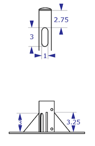
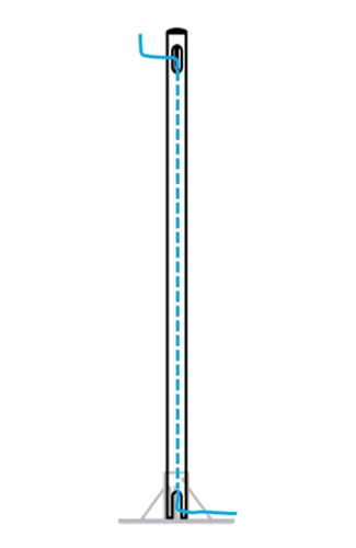
 Wires enter through a 1” by 3” hole near the top of the pole and exit through a similarly sized hole at the base.
WIRE ROUTING
 Both the pole and each base have holes that must be aligned during installation in order to allow the wires to exit from the bottom.
POLE CAPACITY AND WIRE CLIPS
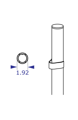
 The inside diameter of the pole is approximately 1.6” and allows for sufficient space for multiple wires to be fed through the entire length of the pole. If there are too many wires to fit through the center pole or they are too large, optional wire clips can be utilized to route the cables alongside the pole.
BASE COVER
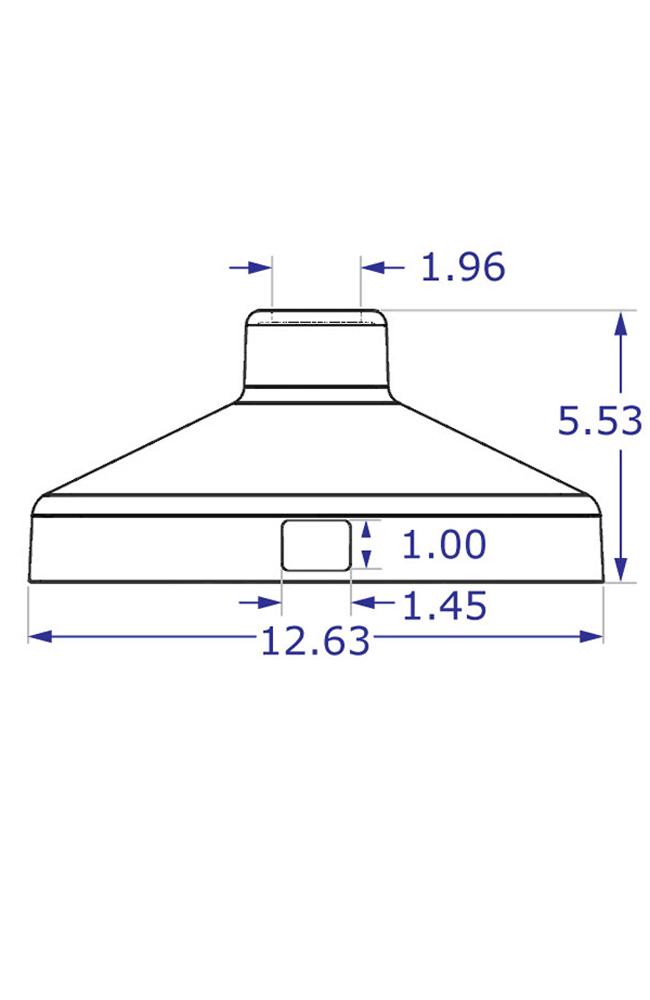
 The optional flange base cover has a 1” by 1.45” access hole that can be oriented in any direction. The covered space also provides additional room to contain, conceal and protect wires and cables.